Beyond the Prototype: Scaling Drone Motor Production to Military Standards with GMW's E-Cam Technology
Beyond the Prototype: Scaling Drone Motor Production to Military Standards with GMW’s E-Cam Technology
In the development of high-power density motors (e.g., electric vehicles or high-performance drones) by GMW Taiwan, the "theoretical space" of the design phase often conflicts with the "physical tolerances" of the production phase. This article explores how automated winding control technology, specifically using electronic cams (E-Cams) and compensation logic, resolves the spatial interference challenges of heavy-gauge wire winding without altering the original design.
Winding Bottlenecks in Drones and High-Density BLDC Motors
✓ Key Technology: E-Cam non-linear linked control.
✓ Proven Results: Slot fill factor increased from 75% to 80%.
✓ Target Audience: Motor R&D teams, defense supply chains, automation equipment buyers.
The Motor Mass Production Dilemma: Why Can't Hand-Wound Samples be Replicated on Automated Lines?
The Core Contradiction Between R&D and Mass Production
With the surging global demand for drone motors and multi-strand parallel-wound BLDC motors, R&D theoretical models often face physical challenges on the production line. Initially, R&D relies on hand-wound samples to verify performance. However, when transitioning to the automated motor manufacturing stage, they face three fatal issues:
✓ Misaligned coil arrangement → Slot fill factor drops by 5-10%.
✓ Uneven phase resistance → Leads to efficiency loss and torque ripple.
✓ Unstable tension control → Enamel insulation ruptures (commonly known as "wire breakage/snapping").
The Key to the Taiwan Supply Chain's Technological Breakthrough
As a professional motor stator winding machine supplier in Taiwan, GMW Taiwan has observed through practical experience: The key to solving mass production bottlenecks is not demanding "zero tolerance" materials, but utilizing the control logic of electronic cam (E-Cam) systems to compensate for physical variables.
This article comprehensively analyzes how non-linear linked technology expands the process window, helping motor R&D teams transition products from design to mass production, covering on-site diagnostics, technical principles, and practical case studies.
On-Site Diagnostics | Why Do Automated Winding Paths Cause Mechanical Interference?
The Root of the Problem: Rigidity of Motion Trajectories vs. Material Tolerances
The most significant difference between automated production and manual prototyping is the rigidity requirement of the motion trajectory. When the physical geometry of the material fluctuates, the pre-allocated safety clearance quickly vanishes, leading to severe mechanical interference. Taking drone BLDC motors as an example:
Stator Core Stack Height Error: The 0.1mm Butterfly Effect
To achieve the ultimate power-to-weight ratio in drone BLDC motors, stator slot space is compressed to the absolute limit. However, during the lamination process, the motor core often develops "stack height errors" due to positive steel sheet thickness tolerances or uneven pressure. A cumulative error of just 0.1mm can have a severe negative impact on the high-speed trajectory of a flyer winding machine.
"When running at high speeds, even a slight excess in stator stack height causes the winding path to deviate, resulting in a violent collision between the wire (or winding nozzle) and the stator ends. This is the primary cause of 'wire breakage' when moving from R&D to mass production."
Overcoming Heavy-Gauge Wire Rigidity: The Physical Logic of Non-Linear Linked Control
Winding heavy-gauge wire requires overcoming high rigidity and springback characteristics. According to electrical principles, a larger wire cross-sectional area yields lower resistance. High-performance motors (like EVs or high-power drones) must use thick wires to reduce heat generation and carry immense currents. However, as copper wire diameter increases, its bending strength rises geometrically, accompanied by strong springback stress after bending. This rebound causes chaotic layering, drastically reducing the slot fill factor—a true nightmare for automated wire routing.
E-Cam Compensation Mechanism for Springback Stress
Traditional winding equipment uses linear feeds, struggling to handle the physical springback of thick copper wire entering the slot. The core advantage of electronic cam (E-Cam) control lies in its ability to create a "non-linear coupling" between the traversing axis and the main winding spindle.
The instant the wire bends into the slot, the control system actively applies a microsecond-level path compensation to counteract the wire's springback stress. This dynamic compensation forces the wire into the exact position, solving the "messy winding" problem common with thick wires and ensuring the physical structure of every turn remains stable.
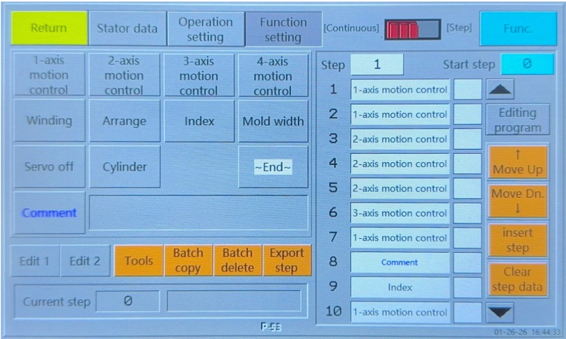
Human-Machine Interface (HMI) screen for configuring electronic cam (E-Cam) path compensation parameters.
Practical Applications in Improving Stator Winding Slot Fill Factor and Alignment
Neat arrangement of motor stator coils is not just for aesthetics; it is crucial for ensuring the symmetry of resistance and inductance across the three-phase windings in BLDC motors, thereby suppressing torque ripple. Simultaneously, a consistent winding structure optimizes thermal conduction paths, preventing localized hot spots and achieving an ideal thermal balance.
Segmented Custom Programming for Physical Stator Asymmetry
To accommodate lead wire structures, the internal space of high-performance stators is often asymmetrically distributed. The HMI provided on GMW motor stator winding machines supports flexible "segmented programming." This allows engineers to set dedicated winding trajectories, wire tension control, and running speeds for specific turn segments (e.g., turns 5-10). Applying this intelligent logic to automated equipment mimics the dynamic adaptability of manual winding while maintaining mass-production level precision.
Achieving "Zero-Crossover, Zero-Overlap" High-Density Wire Arrangement
Through non-linear E-Cam control, GMW precisely guides the landing point of every single wire, achieving a tightly interlocked, honeycomb-like orthocyclic structure. In practice, this technology stably increases the slot fill factor to 80%, maximizing thermal conductivity and torque density within extreme spatial constraints.
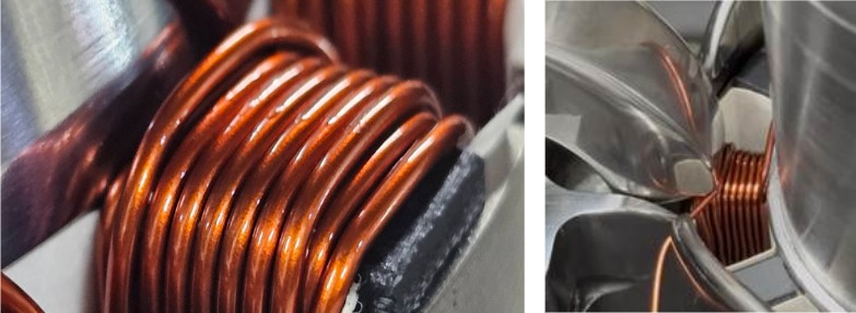
Close-up of perfectly aligned stator coil wires showing a tightly interlocked honeycomb structure for BLDC motors.
Process Parameter Migration: Shortening the R&D to Mass Production Cycle
The Value of Automated Prototyping Services for Process Validation
While hand-wound stator samples can achieve preliminary performance validation, the craft process possesses characteristics that are hard to replicate, making it difficult to directly transform R&D results into standardized digital process assets. If the R&D side can introduce automated winding equipment for trial production in the early stages, it materializes operational experience into analyzable, traceable, and quantifiable data.
Tech Sharing: Enhancing Motor Manufacturability through DFM Optimization
Through actual automated winding tests, the technical team can provide production-effective DFM (Design for Manufacturability) suggestions to the R&D team. For example: fine-tuning the pole shoe R-angle to optimize the wire slip-in path, or adjusting the slot paper height to avoid the flyer's motion trajectory.